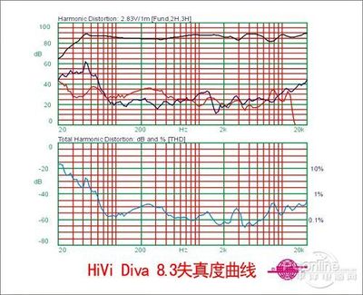
总谐波失真(英文全称Total HarmonicDistortion,THD)是指用信号源输入时,输出信号比输入信号多出的额外谐波成分。功放工作时,由于电路不可避免的振荡或其他谐振产生的二次,三次谐波与实际输入信号叠加,在输出端输出的信号就不单纯是与输入信号完全相同的成分,而是包括了谐波成分的信号,这些多余出来的谐波成分与实际输入信号(基频)的对比,用百分比来表示就称为总谐波失真。
一般来说,总谐波失真在1000赫兹附近最小,所以大部分功放表明总谐波失真是用1000Hz信号做测试,但有些更严格的厂家也提供20-20000赫兹范围内的总谐波失真数据。总谐波失真在1%以下,一般耳朵分辨不出来,超过10%就可以明显听出失真的成分。这个总谐波失真的数值越小,音色就更加纯净。一般产品的总谐波失真都小于1%@1kHz,但这个数值越小,表明产品的品质越高。
| One of theways of expressing the "goodness" of an amplifier or other deviceis to use a number, based on measurements at a given power outputlevel, expressing its "Total Harmonic Distortion." If an amplifieror other device is given a pure sine wave (i.e. just one frequency)at its input, the signal at the output will never be an exact copyof the input. There will always be some deviation in the shape ofthe waveform, which can be expressed as a series of "harmonics" ofthe fundamental frequency. This numberindicatesthe RMS voltage equivalent of totalharmonic distortion power, as a percentage of thetotal output RMS voltage. Clear as mud? Let's say you've got a harmonic analyser or other wayof determining the amount of each harmonic (such as an FFTspectrograph program on your computer). How do you convert thesereadings into a single THD figure, for comparison with otherdevices? Before we go much further, it bears pointing out that there isconsiderable (and very valid) criticism of the practise of a singleTHD number to define the goodness of an amplifier. There areseveral weaknesses to this approach: not all harmonics are equallydiscordant; even harmonics tend to be much less dissonant then oddones; higher harmonics are generally considered more dissonant; anda percentage number does not necessarily relate to how the earperceives sound and distortion. Furthermore, it only describes one"kind" of distortion, and says nothing about intermodulation, phaseerrors, or other anomalies in the audio signal. There have beenattempts to redefine THD to give more "weight" to higher harmonics,and other refinements, but as far as I know the industry has notagreed on any of these modified specs. All that being said, a THDfigurecanbe useful whencombined with other specifications, such as IMD (intermodulationdistortion), etc. Just don't assume that an amplifier with lowerTHD than another will necessarily soundbetter.  Let's first do it thewrongway,even though it appears intuitive. (Follow along with yourcalculator if you really want to understand what's going onhere.)You've got asine-wave generator at, say, 400 Hz. at the input of youramplifier, and set it so that it outputs4 voltsRMSinto an 8-ohmload.You correctly compute the power intothe load (using the formula P=E2/R) as 4*4/8 = 2watts.Let's say you measurethe second harmonic at 0.3 volts RMS, and the third harmonic at 0.5volts.For the sake of this discussion,let's assume that all other harmonics are way in the mud and can beneglected. It doesn't take long to add 0.3 and 0.5 (=0.8), divide by 4 volts,and multiply by 100 to come up with an apparent THDof20%. However, this answerisincorrect. The reason is thatwe have to addPowerand convertto an equivalent voltage. Let's do it the proper way, as summarizedin the table below: |
| Harmonic | Voltage | Power | % Distortion |
| Fundamental | 4.0 volts | 2 watts | |
| 2nd Harm. | 0.3 volts | .01125 W | 0.56225 % |
| 3rd Harm. | 0.5 volts | .03125 W | 1.5625 % |
| Total | .0425 W | 2.12475 % |
"Hey, neat," you may be saying."Only2.12475%!" But we're notthere yet; 2.12475% isanotherwronganswer. While thisapparent THD figure is, indeed, representative of thetotalpowerof the harmoniccontent, we still have to convert this power to anequivalent RMSvoltagein order to come up with a THD figureaccording to standard methodology. |
| THD(%) = 100 * SQRT[(P2+ P3+ P4+ ... + Pn) * Zout] / Vt |
where TDH(%) is total harmonic distortion, P represents the powerof each harmonic, Zoutequals the loadimpedance, andVtis the fundamentalvoltage .
Another way of getting the correct answer would be to takethesquare root of the sum of the squares ofharmonic component voltages. This is because power isproportional to the square of the voltage. Let's try it.SQRT(0.32+0.52) = SQRT(.09 + .25) =SQRT(0.34) = 0.583. Multiply by 100 (to get percent) and divideby4 (fundamentalvoltage)gives thesamecorrectresult,approx.14.6%.
In equation form,
| THD(%) = 100 * SQRT[(V22+ V32+ V42+ ... + Vn2)] / Vt |
where TDH(%) is total harmonic distortion, V represents the RMSvoltage of each harmonic, and Vtisthefundamentalvoltage.
Note that Zoutis not present inthis variant of the equation;
since P = V2/Z, the impedanceterms cancel.
| Working from aSpectrogram |
在labview中将harmonic distortion analyzervi中的highestharmonic设置为5,这个很重要!否则运行的结果用19项谐波计算而用显示的前5项结果计算会导致结果不一致!下面将数据在EXCEL中算了下THD=5.25%与Labview计算的一致,也验证了THD公式的正确性。
| peak value | rms value | rms squred value | |||||||
| Fundamental | 0.9778 | 0.691409011 | 0.47804642 | THD= | 0.0525 | THD公式SQRT(SUM(D3:D6))/C2 | |||
| 2nd | 0.0222 | 0.015697771 | 0.00024642 | ||||||
| 3rd | 0.0406 | 0.028708535 | 0.00082418 | ||||||
| 4th | 0.0101 | 0.007141778 | 0.000051005 | ||||||
| 5th | 0.0198 | 0.014000714 | 0.00019602 | ||||||
You can have a look at the formulae in the"Power" columns and "Totals" rows if you want to understand what'sgoing on here. I hope that some of you will find thisuseful.
 爱华网
爱华网

