概述 General Description
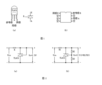
The TL431 is a three-terminal adjustable shunt regulator withguaranteed thermal stability over a full operation range. Itfeatures sharp turn-on characteristics, low temperature coefficientand low output impedance, which make it ideal substitute for Zenerdiode in applications such as switching power supply, charger andother adjustable regulators.
The output voltage of TL431 can be set to any value betweenVref (2.5V) and the corresponding maximum cathodevoltage (40V).
The TL431 is offered in two grade initial voltage tolerance at25℃, 0.5% and 1%.
This IC is available in 3 packages: TO-92 (bulk or ammo), SOT-23and SOT-89.
TL431是三端可调的,全温度范围稳定的并联调整器。具有快速启动、低温漂和低输出阻抗的特性,在开关电源、充电和其他可调调整器应用中是齐纳二极管的理想替代器件。
输出电压范围为Vref (2.5V)到最大阴极电压 (40V)。0.5%和1%两种精度(25℃)。
3种封装:TO-92 (bulk 或 ammo),SOT-23和SOT-89。
特点 Features
可编程精确的输出电压 Programmable Precise Output Voltage from2.5V to 40V
容性负载下高度稳定 High Stability Under Capacitive Load
低阴极电流Low Minimum Cathode Current forRegulation:300µA(Typ.)
低温漂Low Temperature Deviation:7mV Typical
电流能力Sink Current Capacity from 300µA to100mA
低输出噪声Low Output Noise
宽工作温度范围Wide Operating Range:-25℃to125℃
应用 Applications
ü 充电Charger
ü 电压适配器Voltage Adapter
ü 开关电源Switching Power supply
ü 图形卡Graphic Card
ü 精确电压基准Precision Voltage Reference
Figure 1. Package Type of TL431
Pin Configuration
NPackageP Package
(SOT-23)(SOT-89)
ZPackageZ Package
(TO-92(BulkPackage))(TO-92(AmmoPackage))
Figure 2. Pin Configuration of TL431 (TopView)
n 功能框图 Functional BlockDiagram
Figure 3.Functional Block Diagram of TL431
绝对最大额定值 Absolute Maximum Rating (Note 1)
项目 Parameter | 符号 Symbol | 数值 Value | 单位 Unit |
阴极电压 Cathode Voltage | VKA | 40 | V |
阴极电流范围 Cathode Current Range | IKA | -100 to 150 | mA |
参考输入电流范围 Reference Input Current Range | IREF | 10 | mA |
结温 Junction Temperature | TJ | 150 | ℃ |
存储温度 Storage Temperature Range | TSTG | -65 to 150 | ℃ |
ESD(人体模型) ESD(Human Body Model) | ESD | 2000 | V |
Note 1: Stresses greater than those listed under“Absolute Maximum Ratings” may cause permanent damage to thedevice. These are stress ratings only, and functional operation ofthe device at these or any other conditions beyond those indicatedunder “Recommended Operating Conditions” is not implied. Exposureto “Absolute Maximum Ratings” for extended periods may affectdevice reliability.
备注1:超过“绝对最大额定值”的应力可能会造成器件永久损坏。这些仅是应用额定值,器件工作在上述条件以及超出“建议工作条件”的情况是不可取的。长期处于“绝对最大额定值”可能影响器件的可靠性。
n 额定功耗DissipationRating Free-air Temperture(Note 2)
Package | Ta=25℃ Power Rating | Derating Factor Above Ta=25℃ | Ta=70℃ Power Rating | Ta=85℃ Power Rating | Ta=125℃ Power Rating |
TO-92 | 600mW | 6.2mW/℃ | 471 mW | 378 mW | -- |
SOT-89 | 500mW | 4.0mW/℃ | 320 mW | 260 mW | -- |
SOT-23 | 230mW | 1.8mW/℃ | 149 mW | 122 mW | -- |
Note 2:The safe-work power dissipation of TL431 is under0.25W while the package is TO-92 which is the ordinary transistorpackage. Above the power dissipation, the package should be changed to SO or DIP and thedissipation can be to 0.5W. The margin of power should be enoughlarge because the reference voltage will falls as large powerdissipation and high temperature rising. TL431 only is a referencevoltage source. It is used to output a stable reference voltage,not large power.
备注2:TL431的安全使用功率一般设计在0.25W以下(TO-92封装,也就是普通小三极管封装),如果要较大的功率,你可以考虑一下SO封装或DIP封装的,这两种封装的功率设计为0.5W也很稳定。另外之所以给TL431留的功率余量较大,应因为考虑到TL431在大功率,高温升的情况下稳压进度会下降。TL431只是一种基准电压源,它的最大作用是提供稳定的基准电压,而不是输出大功率。
推荐工作条件 Recommended Operating Conditions
项目 Parameter | 符号 Symbol | 最小值 Min | 最大值Max | 单位Unit |
阴极电压 Cathode Voltage | VKA | VREF | 36 | V |
阴极电流 Cathode Current | IKA | 0.3 | 100 | mA |
工作环境温度 Operating Ambient Temperature Range | TA | -25 | 125 | ℃ |
电特性表 Electrical Characteristics
工作条件:除非特指,环境温度25℃
Operating Conditions: TA=25℃, unless otherwisespecified
项目 Parameter | 测试 电路 Test Circuit | 符号 Symbol | 测试条件 Conditions | 数值 Value | 单 位Unit | ||
最小 Min | 典型Typ | 最大Max | |||||
参考电压 Reference Voltage | 4 | VREF | VKA=VREF0.5% 1% | 2.483 2.470 | 2.495 2.495 | 2.507 2.520 | V |
基准电压温漂 Deviation of Reference Voltage Over FullTemperature Range | 4 | ΔVREF | VKA=VREF IKA=10mA -20℃ to 110℃ | 10 | 13 | mV | |
基准电压的线性调整率 Ratio of Change in Reference Voltage to theChange in Cathode Voltage | 5 | ΔVREF ΔVKA | IKA=5mAVKA=10VtoVREF | 0.53 | mV/V | ||
IKA=5mA VKA=36Vto10V | 0.2 | ||||||
基准电流 Reference Current | 5 | IREF | IKA=10mA R1=10KΩ R2=∞ | 0.200 | 0.5 | µA | |
基准电流温漂 Deviation of Reference Current Over FullTemperature Range | 5 | ΔIREF | IKA=10mA R1=10KΩ R2=∞ TA=-10℃ to 85℃ | 0.08 | 0.092 | µA | |
最小阴极电流 Minimum Cathode Current for Regulation | 4 | IKA(Min) | VKA=VREF | 300 | 400 | µA | |
夹断阴极电流 Off-state Cathode Current | 6 | IKA(Off) | VKA=36V VREF=0 | 0.03 | µA | ||
动态阻抗 Dynamic Impedance | 4 | ZKA | VKA=VREF IKA=1 to 100mA  f≤1.0KHz | 0.2 | 0.5 | Ω | |
热阻 Thermal Resistance | θJC | TO-92 | 68 | ℃/W | |||
SOT-89 | 70 | ||||||
SOT-23 | 113 | ||||||
Figure 4. Test Circuit 4 forVKA=VREF
Figure 5. Test Circuit 5 forVKA=VREF(1+R1/R2)+IREF*R1
Figure 6. Test Circuit 6 forIOFF
典型性能 Typical Performance Characteristics
Figure 7. Reference Voltage vs. AmbientTemperatureFigure 8. Reference Current vs. AmbientTemperature
Figure 9. Cathode Current vs. Cathode VoltageFigure10. Cathode Current vs. Cathode Voltage
Figure 11. Off-state Cathode Current vs.Figure12.Ratio of Delta Reference Voltage to the
Ambient TemperatureRatioof Delta Cathode Voltage
Figure 13. Small Signal Voltage Gain vs.Frequency
Figure 14. Stability Boundry Conditions vs.Capacitance
Figure 15. Pulse Response of Input and OutputVoltage
典型应用 Typical Application
Figure 16. ShuntRegulatorFigure 17. High Current Shunt Regulator
Figure 18. Current Source or CurrentLimitFigure 19. Precision 5V 1A Regulator
Figure 20. PWM Converter withReference
外观尺寸 Mechanical Dimensions
TO-92 (BulkPacking)Unit: mm(inch)
外观尺寸 Mechanical Dimensions (Continued)
TO-92 (AmmoPacking)Unit: mm (inch)
外观尺寸 Mechanical Dimensions (Continued)
SOT-89Unit: mm (inch)
外观尺寸 Mechanical Dimensions (Continued)
SOT-23Unit:mm (inch)
 爱华网
爱华网


