帧中继基本配置
1、实验目的
通过本实验可以掌握:
A.帧中继的基本配置;
B.帧中继的动态映射;
C.帧中继的静态映射;
D.帧中继上RIP的配置;
E.接口水平分割的开启与关闭
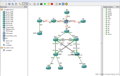
2、实验拓扑
3、实验步骤
R1:
R1#conf t
Enter configuration commands, one perline. Endwith CNTL/Z.
R1(config)#int s1/0
R1(config-if)#ip address 192.168.134.1255.255.255.0
R1(config-if)#encapsulation frame-relay //接口封装帧中继
R1(config-if)#frame-relay lmi-type cisco //配置接口的LMI类型
R1(config-if)#no shutdown
R1(config-if)#exit
R1(config)#int lo0
R1(config-if)#ip address 192.168.1.1255.255.255.0
R1(config)#router rip
R1(config-router)#version 2
R1(config-router)#network192.168.134.0
R1(config-router)#network192.168.1.0
【提示】
如果采用的Cisco路由器的IOS是11.2及以后版本的,路由器可以自动协商LMI的类型,所以可以不配置。
R3:
R3#conf t
Enter configuration commands, one perline. Endwith CNTL/Z.
R3(config)#int s1/1
R3(config-if)#ip address 192.168.134.3255.255.255.0
R3(config-if)#encapsulation frame-relay
R3(config-if)#frame-relay lmi-type cisco
R3(config-if)#no shutdown
R3(config-if)#exit
R3(config)#int lo0
R3(config-if)#ip address 192.168.3.1255.255.255.0
R3(config-if)#no sh
R3(config-if)#exit
R3(config)#router rip
R3(config-router)#version 2
R3(config-router)#noauto-summary
R3(config-router)#network192.168.134.0
R3(config-router)#network192.168.3.0
R4:
R4#conft
Enterconfiguration commands, one per line. End withCNTL/Z.
R4(config)#int s1/2
R4(config-if)#ip address 192.168.134.4255.255.255.0
R4(config-if)#encapsulation frame-relay
R4(config-if)#frame-relay lmi-typecisco
R4(config-if)#no sh
R4(config-if)#exit
R4(config)#int lo0
R4(config-if)#ip address 192.168.4.1255.255.255.0
R4(config-if)#no sh
R4(config-if)#exit
R4(config)#router rip
R4(config-router)#version 2
R4(config-router)#network 192.168.134.0
R4(config-router)#network 192.168.4.0
R2:帧中继配置
R2#conft
Enterconfiguration commands, one per line. End withCNTL/Z.
R2(config)#frame-relay switching
R2(config)#int s1/0
R2(config-if)#clock rate 64000
R2(config-if)#encapsulation frame-relay
R2(config-if)#frame-relay lmi-typecisco
R2(config-if)#frame-relay intf-type dce
R2(config-if)#frame-relay route 103 interface s1/1301
R2(config-if)#frame-relay route 104 interface s1/2401
R2(config-if)#no sh
R2(config-if)#exit
R2(config)#int s1/1
R2(config-if)#clock rate 64000
R2(config-if)#encapsulation frame-relay
R2(config-if)#frame-relay route 301 interface s1/0103
R2(config-if)#frame-relay route 304 interface s1/2403
R2(config-if)#frame-relay lmi-typecisco
R2(config-if)#frame-relay intf-type dce
R2(config-if)#no sh
R2(config-if)#exit
R2(config)#int s1/2
R2(config-if)#clock rate 64000
R2(config-if)#encapsulation frame-relay
R2(config-if)#frame-relay lmi-typecisco
R2(config-if)#frame-relay intf-type dce
R2(config-if)#frame-relay route 401 interface s1/0104
R2(config-if)#frame-relay route 403 interface s1/1304
R2(config-if)#no sh
4、实验调试
A、show frame-relaymap
该命令用来查看帧中继的映射
R1#showframe-relay map
Serial1/0(up): ip 192.168.134.3 dlci 103(0x67,0x1870), dynamic,
broadcast,
CISCO, status defined,active
Serial1/0(up): ip 192.168.134.4 dlci 104(0x68,0x1880), dynamic,
broadcast,, statusdefined, active
R1#
R3#showframe-relay map
Serial1/1(up): ip 192.168.134.1 dlci 301(0x12D,0x48D0), dynamic,
broadcast,
CISCO, status defined,active
Serial1/1(up): ip 192.168.134.4 dlci 304(0x130,0x4C00), dynamic,
broadcast,, statusdefined, active
R3#
R4#showframe-relay map
Serial1/2(up): ip 192.168.134.1 dlci 401(0x191,0x6410), dynamic,
broadcast,, statusdefined, active
Serial1/2(up): ip 192.168.134.3 dlci 403(0x193,0x6430), dynamic,
broadcast,, statusdefined, active
R4#
以上输出显示了帧中继逆向ARP的作用结果,表明路由器R1、R3和R4每个封装帧中继的接口都包含2条处于活动(active)状态的DLCI;每条记录都显示了远端的IP地址和本地的DLCI的映射关系;“broadcast”参数允许在PVC上传输广播货组播流量;“dynamic”表明是动态映射。
【提示】
以上实验我们注意到,每天路由器都不能ping通自己的串行口IP地址,但是可以ping通远端封装帧中继的串行口IP地址,因为自己的帧中继映射表中没有自己接口IP地址和DLCI的映射条目。采用逆向ARP做动态映射是解决不了该问题的,只有通过静态映射解决。
B、show frame-relaypvc
R1#show frame-relay pvc
PVC Statistics forinterface Serial1/0 (Frame Relay DTE)
//接口是帧中继的DTE
ActiveInactiveDeletedStatic
Local2000
Switched0000
Unused0000
//输出表明该接口有2条处于活跃状态的PVC
DLCI = 103, DLCI USAGE = LOCAL,PVC STATUS = ACTIVE, INTERFACE = Serial1/0
//DLCI为103的PVC处于活跃状态,本地接口是S1/0,DLCI用途是LOCAL
DLCI = 104, DLCI USAGE = LOCAL,PVC STATUS = ACTIVE, INTERFACE = Serial1/0
【技术要点】
PVC状态有如下3种,每种的含义如下所述:
i.ACTIVE:表明PVC的状态是活跃的,表示成功的端对端(DTE到DTE)电路。
ii.INACTIVE:表明成功连接到交换机,但在PVC的另一端未检测到DTE。
iii.DELETED:表明为该DTE配置的DLCI被交换机视为对该接口无效,或PVC不存在。
C、show frame-relaylmi
R1#show frame-relay lmi
LMI Statistics forinterface Serial1/0 (Frame Relay DTE) LMI TYPE = CISCO
//接口S1/0是帧中继的DTE,LMI类型为Cisco
Invalid Unnumberedinfo 0Invalid Prot Disc 0
Invalid dummy CallRef 0Invalid Msg Type 0
Invalid StatusMessage 0Invalid Lock Shift 0
Invalid InformationID 0Invalid Report IE Len 0
Invalid ReportRequest 0Invalid Keep IE Len 0
Num Status Enq. Sent 325Num Status msgs Rcvd 201
//路由器向帧中继交换机发送的LMI状态查询消息的数量以及路由器从帧中继交换机收到到LMI状态信息的数量
Num Update StatusRcvd 0Num Status Timeouts 124
Last Full Status Req00:00:20Last Full Status Rcvd 00:00:20
R1#
D、show ip routerip
R1#show ip route rip
R192.168.4.0/24 [120/1] via 192.168.134.4, 00:00:08,Serial1/0
R192.168.3.0/24 [120/1] via 192.168.134.4, 00:00:08,Serial1/0
[120/1] via 192.168.134.3, 00:00:19, Serial1/0
R1#
R3#sh ip route rip
R192.168.4.0/24 [120/1] via 192.168.134.4, 00:00:24,Serial1/1
[120/1] via 192.168.134.1, 00:00:21, Serial1/1
R192.168.1.0/24 [120/1] via 192.168.134.4, 00:00:24,Serial1/1
[120/1] via 192.168.134.1, 00:00:21, Serial1/1
R3#
R4#sh ip route rip
R192.168.1.0/24 [120/1] via 192.168.134.1, 00:00:09,Serial1/2
R192.168.3.0/24 [120/1]via 192.168.134.3, 00:00:19, Serial1/2
[120/1] via 192.168.134.1, 00:00:09, Serial1/2
R4#
以上输出表明各路由器的RIP路由信息正确。在本实验中,帧中继交换机在路由器R2上采用了PVC全互联的拓扑结构,但是在实际应用中,为了节省费用,一般采用中心-分支(Hub-and-Spoke)的拓扑结构,即只有分支到中心的PVC,假如路由器R1是中心路由器,路由器R2和R3是分支路由器,在路由器R2的配置修改如下:
R2(config)#int s1/1
R2(config-if)#no frame-relay route 304
R2(config)#int s1/2
R2(config-if)#no frame-relay route 403
此时再次查看路由表:
R1#show ip route rip
R192.168.4.0/24 [120/1] via 192.168.134.4, 00:00:22,Serial1/0
R192.168.3.0/24 [120/1] via 192.168.134.4, 00:00:22,Serial1/0
[120/1] via 192.168.134.3, 00:00:17, Serial1/0
R1#
R3#sh ip route rip
R192.168.4.0/24 [120/1] via 192.168.134.1, 00:00:22,Serial1/1
R192.168.1.0/24 [120/1] via 192.168.134.1, 00:00:22,Serial1/1
R3#
R4#sh ip route rip
R192.168.1.0/24 [120/1] via 192.168.134.1, 00:00:07,Serial1/2
R192.168.3.0/24 [120/1] via 192.168.134.1, 00:00:07,Serial1/2
R4#
E、配置帧中继静态映射
R1(config)#int s1/0
R1(config-if)#no frame-relayinverse-arp//关闭逆向ARP,默认是开启的
R1(config-if)#frame-relay map ip 192.168.134.3 103broadcast
//配置帧中继静态映射
R1(config-if)#frame-relay map ip 192.168.134.4 104broadcast
R1(config-if)#frame-relay map ip 192.168.134.1 104broadcast
//配置到自己接口的IP地址的映射,目的是允许ping路由器该接口的IP地址
R3(config)#int s1/1
R3(config-if)#no frame-relayinverse-arp
R3(config-if)#frame-relay map ip192.168.134.1 301 broadcast
R3(config-if)#frame-relay map ip192.168.134.3 301 broadcast
R3(config-if)#frame-relay mapip 192.168.134.4 301 broadcast
R4(config)#int s1/2
R4(config-if)#no frame-relayinverse-arp
R4(config-if)#frame-relay mapip 192.168.134.1 401 broadcast
R4(config-if)#frame-relay mapip 192.168.134.3 401 broadcast
R4(config-if)#frame-relay mapip 192.168.134.4 401 broadcast
i.Show frame-relaymap
R1#show frame-relay map
Serial1/0 (up): ip 192.168.134.1 dlci104(0x68,0x1880), static,
broadcast,
CISCO, status defined,active
Serial1/0 (up): ip 192.168.134.3 dlci103(0x67,0x1870), static,
broadcast,
CISCO, status defined,active
Serial1/0 (up): ip 192.168.134.4 dlci104(0x68,0x1880), static,
broadcast,
CISCO, status defined,active
R1#
R3#show frame-relay map
Serial1/1 (up): ip 192.168.134.1 dlci301(0x12D,0x48D0), static,
broadcast,
CISCO, status defined,active
Serial1/1 (up): ip 192.168.134.3 dlci301(0x12D,0x48D0), static,
broadcast,
CISCO, status defined,active
Serial1/1 (up): ip 192.168.134.4 dlci301(0x12D,0x48D0), static,
broadcast,
CISCO, status defined,active
R3#
R4#show frame-relay map
Serial1/2 (up): ip 192.168.134.1 dlci401(0x191,0x6410), static,
broadcast,
CISCO, status defined,active
Serial1/2 (up): ip 192.168.134.3 dlci401(0x191,0x6410), static,
broadcast,
CISCO, status defined,active
Serial1/2 (up): ip 192.168.134.4 dlci401(0x191,0x6410), static,
broadcast,
CISCO, status defined,active
R4#
以上输出表明路由器R1、R3和R4每个封装了帧中继的接口下都采用静态映射
ii.查看路由表
R1#sh ip route rip
R192.168.4.0/24 [120/1] via 192.168.134.4, 00:00:04,Serial1/0
R192.168.3.0/24 [120/1] via 192.168.134.4, 00:00:04,Serial1/0
[120/1] via 192.168.134.3, 00:00:03, Serial1/0
R1#
R3#sh ip route rip
R192.168.4.0/24 [120/1] via 192.168.134.1, 00:00:10,Serial1/1
R192.168.1.0/24 [120/1] via 192.168.134.1, 00:00:10,Serial1/1
R3#
R4#sh ip route rip
R192.168.1.0/24 [120/1] via 192.168.134.1, 00:00:22,Serial1/2
R192.168.3.0/24 [120/1] via 192.168.134.1, 00:00:22,Serial1/2
R4#
以上输出表明各路由器的RIP路由信息正确,但是与上面动态映射实验的路由表相比,路由器R3的路由表中路由器R4环回口网络和路由器R4的路由表中路由器R3环回口网络的下一跳发生了变化,都指向路由器R1。
F、水平分割问题:
R1#sh ip int s1/0
Serial1/0 is up, line protocol isup
Internet address is192.168.134.1/24
Broadcast address is255.255.255.255
Address determined bysetup command
MTU is 1500bytes
Helper address is notset
Directed broadcastforwarding is disabled
Multicast reservedgroups joined: 224.0.0.9
Outgoing access listis not set
Inbound access list is notset
Proxy ARP isenabled
Local Proxy ARP isdisabled
Security level isdefault
Split horizon isdisabled//接口封装了帧中继哦,水平分割被自动关闭。
在R1上重新打开水平分割,在各路由器上检查路由表
R1(config)#int s1/0
R1(config-if)#ip split-horizon//开启水平分割
R1#clear iproute *//清除路由表
R1#sh ip route rip
R192.168.4.0/24 [120/1] via 192.168.134.4, 00:00:13,Serial1/0
R192.168.3.0/24 [120/1] via 192.168.134.3, 00:00:26,Serial1/0
R1#
//R1可以获得路由器R3和R4的环回口网络的路由
R3#sh ip route rip
R192.168.1.0/24 [120/1] via 192.168.134.1, 00:00:10,Serial1/1
R3#
//路由器R3只能获得路由器R1的环回口网络的路由,这是由于路由器R1上水平分割开启后,路由器R1从路由器R4接收到路由器R4通告的路由后,受水平分割限制,不能从封装帧中继的接口发送出来,导致路由器R3没有接收到路由器R4上通告的路由。
R4#sh ip route rip
R192.168.1.0/24 [120/1] via 192.168.134.1, 00:00:09,Serial1/2
R4#
//同理,路由器R4也只能获得路由器R1的环回口网络的路由。